OptiFiber® Pro OTDR Family
Key features
- Multiple wavelengths (850, 1300, 1310,1490, 1550 and 1625 nm) support LAN, datacenters, PON, FTTx and outside plant applications.
- Automated setup senses fiber characteristics and sets measurement parameters
- Manual Expert mode allows simple adjustments to automated settings for detailed testing.
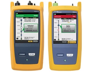
- EventMap automatically identifies events including connectors, splices, bends, and splitters
- product overview
- specifications
- What's in the box
Product overview: OptiFiber® Pro OTDR Family
Designed for Enterprise, Datacenter, Outside Plant and PON Fiber
As fiber networks evolve, the need to test in more locations has increased. OTDRs are now needed for:
- FTTx
- Enterprise
- OSP
- PON
- POLAN
Many OTDRs designed for fiber troubleshooting are designed for carrier and contain cumbersome and complicated features. The OptiFiber Pro OTDR family is the first class of OTDRs that is built with features and usability for both the enterprise network engineers, and cable installers working in both enterprise and OSP environments.
Other features:
- Gesture-based interface allows fast, in-depth trace analysis
- SmartLoop™ OTDR technology tests two fibers in a single test eliminating the need to travel to the far end of the connection to perform tests.
- Instantaneous on-board bi-directional averaging results included as standard
- Integrates with LinkWare™ Live to manage jobs and testers from any smart device.
- Future-ready VersivTM design supports copper certification to Category 8, fiber loss and inspection.
Specifications: OptiFiber® Pro OTDR Family
Key OptiFiber Pro OTDR specifications
| Multimode Module | Singlemode Module | Quad Module | |
|---|---|---|---|
| Wavelengths | 850 nm +/- 10 nm 1300 nm +35/-15 nm | 1310 nm +/- 25 nm 1550 nm +/- 30 nm | 850 nm +/- 10 nm 1300 nm +35/-15 nm 1310 nm +/- 25 nm 1550 nm +/- 30 nm |
| Compatible fiber types | 50/125 µm 62.5/125 µm | Singlemode | 50/125 µm 62.5/125 µm Singlemode |
| Event dead zone 1 | 850 nm: 0.5 m typical 1300 nm: 0.7 m typical | 1310 nm: 0.6 m typical 1550 nm: 0.6 m typical | 850 nm: 0.5 m typical 1300 nm: 0.7 m typical 1310 nm: 0.6 m typical 1550 nm: 0.6 m typical |
| Attenuation dead zone 2 | 850 nm: 2.5 m typical 1300 nm: 4.5 m typical | 1310 nm: 3.6 m typical 1550 nm: 3.7 m typical | 850 nm: 2.5 m typical 1300 nm: 4.5 m typical 1310 nm: 3.6 m typical 1550 nm: 3.7 m typical |
| Dynamic range 3, 5, 6 | 850 nm: 28 dB typical 1300 nm: 30 dB typical | 1310 nm: 32 dB typical 1550 nm: 30 dB typical | 850 nm: 28 dB typical 1300 nm: 30 dB typical 1310 nm: 32 dB typical 1550 nm: 30 dB typical |
| Max distance range setting | 40 km | 130 km | MM: 40 km SM: 130 km |
| Distance measurement range 4, 5, 7, 8, 9, 10 | 850 nm: 9 km 1300 nm: 35 km | 1310 nm: 80 km 1550 nm: 130 km | 850 nm: 9 km 1300 nm: 35 km 1310 nm: 80 km 1550 nm: 130 km |
| Reflectance range 4, 5 | 850 nm: -14 dB to -57 dB (typical) 1300 nm: -14 dB to -62 dB (typical) | 1310 nm: -14 dB to -65 dB (typical) 1550 nm: -14 dB to -65 dB (typical) | 850 nm: -14 dB to -57 dB (typical) 1300 nm: -14 dB to -62 dB (typical) 1310 nm: -14 dB to -65 dB (typical) 1550 nm: -14 dB to -65 dB (typical) |
| Sample resolution | 3 cm to 400 cm | 3 cm to 400 cm | 3 cm to 400 cm |
| Pulse widths (nominal) | 850 nm: 3, 5, 20, 40, 200 ns 1300 nm: 3, 5, 20, 40, 200, 1000 ns | 1310/1550 nm: 3, 10, 30, 100, 300, 1000, 3000, 10000, 20000 ns | 850 nm: 3, 5, 20, 40, 200 ns 1300 nm: 3, 5, 20, 40, 200, 1000 ns 1310/1550 nm: 3, 10, 30, 100, 300, 1000, 3000, 10000, 20000 ns |
| Test time (per wavelength) | Auto setting: 5 sec (typical) Quick test setting: 2 sec (typical) Best resolution setting: 2 to 180 sec FaultMap setting: 2 sec (typical), 180 sec (max) DataCenter OTDR setting: 1 sec (typical at 850 nm), 7 sec (max) Manual setting: 3, 5, 10, 20, 40, 60, 90, 120, 180 sec | Auto setting: 10 sec (typical) Quick test setting: 5 sec (typical) Best resolution setting: 5 to 180 sec FaultMap setting: 10 sec (typical), 180 sec (max) DataCenter OTDR setting: 20 sec (typical), 40 sec (max) Manual setting: 3, 5, 10, 20, 40, 60, 90, 120, 180 sec | Auto setting: MM – 5 sec (typical) SM – 10 sec (typical) Quick test setting: MM – 2 sec (typical) SM – 5 sec (typical) Best resolution setting: MM – 2 to 180 sec SM – 5 to 180 sec FaultMap setting: MM - 2 sec (typical), MM - 180 sec (max) SM - 10 sec (typical), SM - 180 sec (max) DataCenter OTDR setting: MM – 1 sec (typical at 850 nm), MM – 7 sec (max) SM – 20 sec (typical), SM – 40 sec (max) Manual setting: 3, 5, 10, 20, 40, 60, 90, 120, 180 sec |
1. Measured at 1.5 dB below non-saturating reflection peak with the shortest pulse width. Reflection peak < -40 dB for multimode and < - 50 dB for singlemode.
2. Measured at +/- 0.5 dB deviation from backscatter with the shortest pulse width. Reflection peak < -40 dB for multimode and < - 50 dB for singlemode.
3. For typical backscatter coefficient for OM1 fiber: 850: -65 dB, 1300: -72 dB.
4. Typical backscatter and attenuation coefficients for OM2-OM4 fiber: 850 nm: -68 dB; 2.3 dB/km: 1300 nm: -76 dB; 0.6 dB/km.
5. Typical backscatter and attenuation coefficients for OS1-OS2 fiber: 1310nm : -79 dB; 0.32 dB/km; 1550 nm: -82 dB; 0.19 dB/km.
6. SNR=1 method, 3 minute averaging, widest pulse width.
7. 850 = 9 km typical to find the end or 7 km typical to find a 0.1 dB event (with a maximum of 18 dB attenuation prior to the event).
Key OptiFiber Pro HDR Specifications
| Specification | HDR Config 1 | HDR Config 2 | HDR Config 3 |
|---|---|---|---|
| Wavelengths | 1310 nm +/- 25 nm 1550 nm +/- 20 nm | 1310 nm +/- 25 nm 1490 nm +/- 20 nm 1550 nm +/- 20 nm | 1310 nm +/- 25 nm 1550 nm +/- 20 nm 1625 nm +/- 20 nm |
| Compatible fiber types | Singlemode | Singlemode | Singlemode |
| OTDR Port Connector | Cleanable APC ferrule with removable SC adapter | Cleanable APC ferrule with removable SC adapter | Cleanable APC ferrule with removable SC adapter |
| Event dead zone 1 | 0.7 m (typical) | 0.7 m (typical) | 0.7 m (typical) |
| Attenuation dead zone 2 | 4 m (typical) | 4 m (typical) | 4 m (typical) |
| PON dead zone 3 | 30 m (typical) | 30 m (typical) | 30 m (typical) |
| Max distance range setting | 260 km | 260 km | 260 km |
| Dynamic range 4, 5 | 1310 nm: 42 dB (typical) 1550 nm: 41 dB (typical) | 1310 nm: 42 dB (typical) 1490 nm: 41 dB (typical) 1550 nm: 41 dB (typical) | 1310 nm: 42 dB (typical) 1550 nm: 41 dB (typical) 1625 nm: 40 dB (typical) |
| Reflectance range 4 | -14 to -70 dB (typical) | -14 to -70 dB (typical) | -14 to -70 dB (typical) |
| Sampling resolution | 3 cm to 2 m | 3 cm to 2 m | 3 cm to 2 m |
| Sampling points | Up to 129000 | Up to 129000 | Up to 129000 |
| Pulse widths (nominal) | 5, 10, 30, 50, 100, 300, 500, 1000, 3000, 5000, 10000, 20000 ns | 5, 10, 30, 50, 100, 300, 500, 1000, 3000, 5000, 10000, 20000 ns | 5, 10, 30, 50, 100, 300, 500, 1000, 3000, 5000, 10000, 20000 ns |
| Distance uncertainty | +/-(1 + 0.0005×distance + 0.5×resolution) | +/-(1 + 0.0005×distance + 0.5×resolution) | +/-(1 + 0.0005×distance + 0.5×resolution) |
| Linearity | ±0.03 dB/dB | ±0.03 dB/dB | ±0.03 dB/dB |
| Reflectance uncertainty | ±2 dB | ±2 dB | ±2 dB |
| Test Time (per wavelength) | Auto setting: 5 sec/wavelength (typical) Auto PON setting: 10 sec/wavelength (typical) Manual setting: 3, 5, 10, 20, 40, 60, 90, 120, 180 sec/wavelength Manual PON setting: 3, 5, 10, 20, 40, 60, 90, 120, 180 sec/wavelength Quick test: 3 sec/wavelength (typical) Best resolution: 5 to 180 sec/wavelength | Same as left | Same as left |
| Laser Classification | Class 1 CDRH Complies to EN 60825-2, 3rd Edition | Class 1 CDRH Complies to EN 60825-2, 3rd Edition | Class 1 CDRH Complies to EN 60825-2, 3rd Edition |
| Calibration Period | 1 year | 1 year | 1 year |
1. Measured at 1.5 dB below non-saturating reflection peak with the shortest pulse width. Reflection peak at - 50 dB.
2. Measured at +/- 0.5 dB deviation from backscatter with the shortest pulse width. Reflection peak‹ - 50 dB.
3. Measured at +/- 0.5 dB deviation from backscatter after 1:16 non-reflective splitter using 50 ns pulse width and 3 cm sampling resolution.
4. Typical backscatter coefficients for OS1-OS2 fiber: 1310 nm: -79 dB; 1490 nm: -81 dB; 1550 nm: -82 dB; 1625 nm: -84 dB.
5. 3 minute averaging, widest pulse width, 100 km fiber length, SNR = 1.
Additional Key Specifications
FiberInspector Probe Specification
| Parameter | Value |
|---|---|
| Magnification | ~ 200X with OptiFiber Pro Display |
| Light source | Blue LED |
| Power source | Versiv mainframe |
| Field of View (FOV) | Horizontal: 425 µm Vertical: 320 µm |
| Minimum detectable particle size | 0.5 µm |
| Dimensions | Approximately 6.75 in x 1.5 in (1175 mm x 35 mm) without adapter tip |
| Weight | 200 g |
| Temperature range | Operating: 32°F to 122°F (0 °C to +50 °C) Storage: -4°F to +158°F (-20°C to +70°C) |
| Certifications | CE (when used with the mainframe) |
VFL Specifications
| Parameter | Value |
|---|---|
| On/Off control | Mechanical switch and a button on the touch screen |
| Output power | 316 µW (-5 dBm) = peak power = 1.0 mW (0 dBm) |
| Operating wavelength | 650 nm nominal |
| Spectral width (RMS) | ±3 nm |
| Output modes | Continuous wave Pulsed mode (2 Hz to 3 Hz blink frequency) |
| Connector adapter | 2.5 mm universal |
| Laser safety (classification) | Class II CDRH Complies to EN 60825-2 |
General Specifications
| Parameter | Value |
|---|---|
| Weight | Mainframe with module and battery: 3 lbs, 5 oz (1.28 kg) |
| Dimensions | Mainframe with module and battery: 2.625 in x 5.25 in x 11.0 in (6.67 cm x 13.33 cm x 27.94 cm) |
| Battery | Lithium ion battery pack, 7.2 volts |
| Battery life | Eight hour Auto OTDR operation, dual wavelength, no video probe connected, 150 m of fiber |
| Integrated Wi-Fi | Meets IEEE 802.11 a/b/g/n; dual band (2.4 GHz and 5 GHz) |
Charge Time
| Mode | Charge Time |
|---|---|
| Tester Off | Four hours to charge from 10% to 90% capacity |
| Tester On | Six hours to charge from 10% to 90% capacity with the tester on |
Environmental Specifications
| Parameter | Value |
|---|---|
| Operating temperature* | -10ºC to 45ºC |
| Storage temperature | -10ºC to +60ºC |
| Operating altitude | 4,000 m (13123 ft) 3200 m (10,500 ft) with ac adapter |
| Storage altitude | 12,000 m |
| EMC | EN 61326-1 |
* Using battery power. With AC power: 0ºC to 45ºC. Real Time Trace function used for no more than 5 minutes in a 15-minute period. Maximum ambient temperature is 35ºC for continuous use of the Real Time Trace function.
* Do not keep battery at temperatures below -20°C (-4°F) or above 50°C (122°F) for periods longer than one week to maintain battery capacity.